This guy bops
These sorts of projects are all over. From this Raspberry Pi Super Nintendo to a Modern System in a 386 case to a Ryzen in a TRS80 to — perhaps my personal favorite — this PC in an old Philco radio, giving new life to an enclosure designed decades ago has a certain magic to it. I stumbled upon the chassis for this build while on Craigslist scavenging for parts for another build, and at $30 I couldn't say no. Even if I just used it as an external display or stuffed a Raspberry Pi into it for a low powered linux machine, I could get some use out of it (in retrospect this is a bad way to justify purchases).
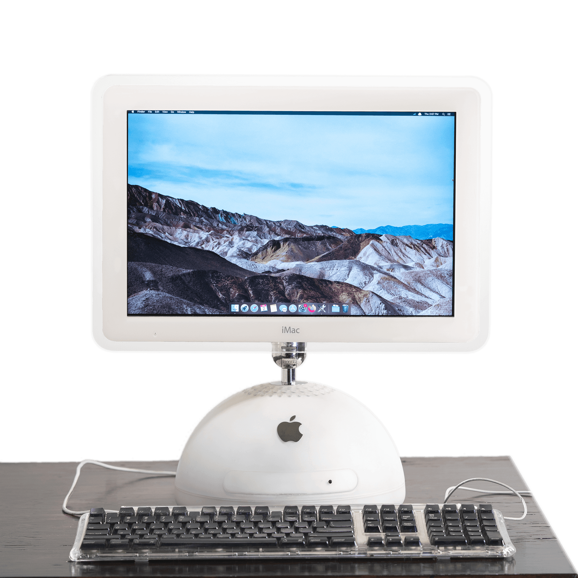
Although its internals make it ancient in computer terms, the design is striking: unlike anything Apple had done before, with its flat panel screen and hemispherical base, and visually revolutionary in a way that few of their devices have been since. Just look how cute it is in the ad. Beautiful exterior and garbage components: perfect for a retrofit.
Initial Impressions
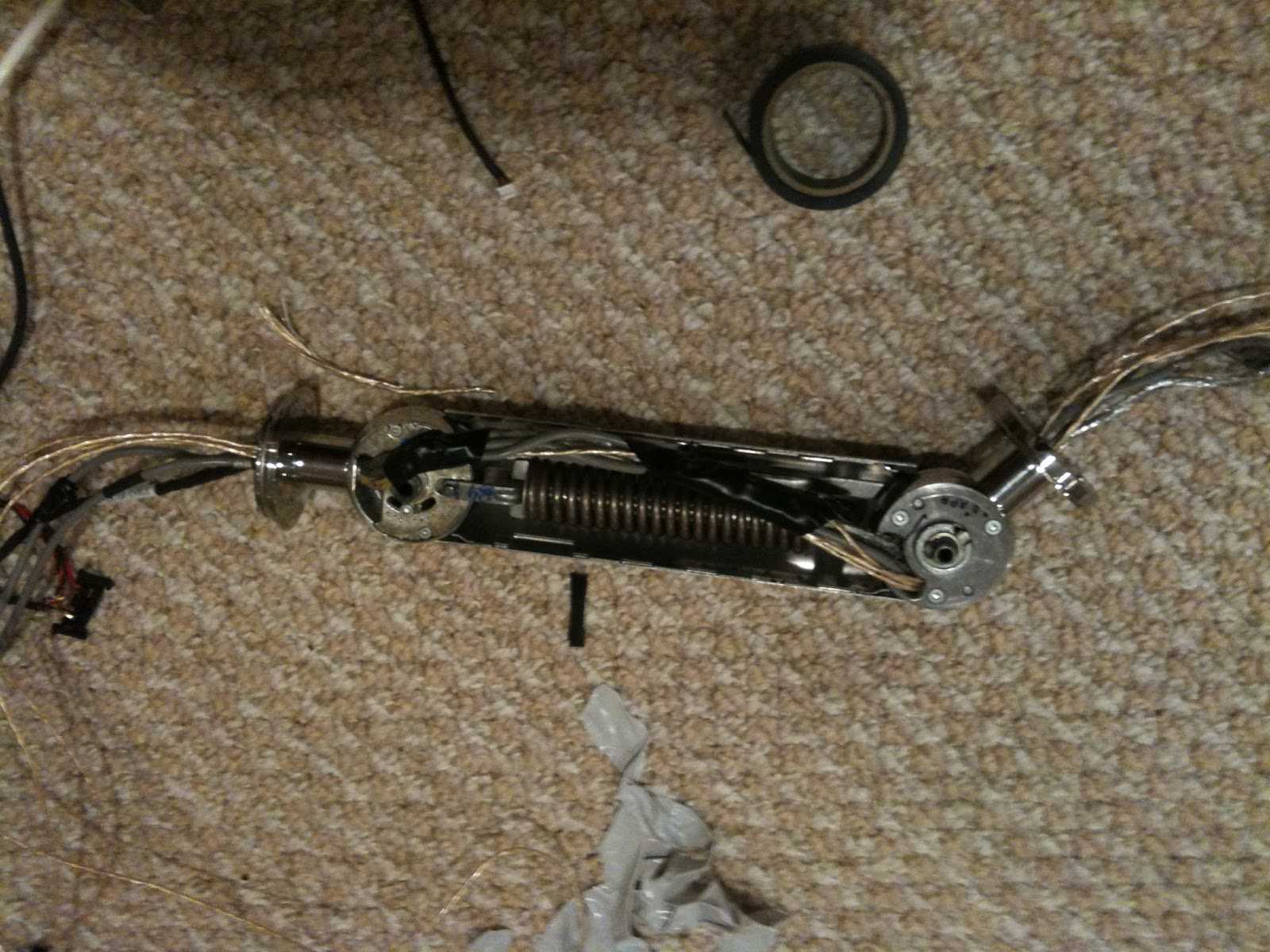
The device is a circa 2002 iMac G4 800 17" with a blazing fast 800MHz PowerPC processor, 256MB SDRAM, an 80GB HDD, and an included Apple Pro Mouse and Keyboard set. I knew when I got it that the display was nonfunctional, but I didn't mind having to upgrade the 1440x900 screen to a 1920x1200 one. My plan was to do a pretty simple swap and reuse both the backlight inverter in the display assembly as well as the LVDS wiring already running through the goose neck (there's some debate on what the pivot arm should be called, so I hope this video of geese eating apples will convince you). 17" replacement LCDs and their driver boards are easy to find online since it's a common size for larger laptops.
As a tribute to a respectable piece of hardware — and to see what would happen — I tried powering on the machine. The sounds of the cooling fan and hard disk spinning greeted me, but the blank screen was a little concerning. I wasn't expecting to see an output image, but the lack of a backlight gave a little insight into the problems I would later face.
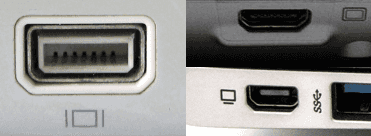
All "mini VGA"
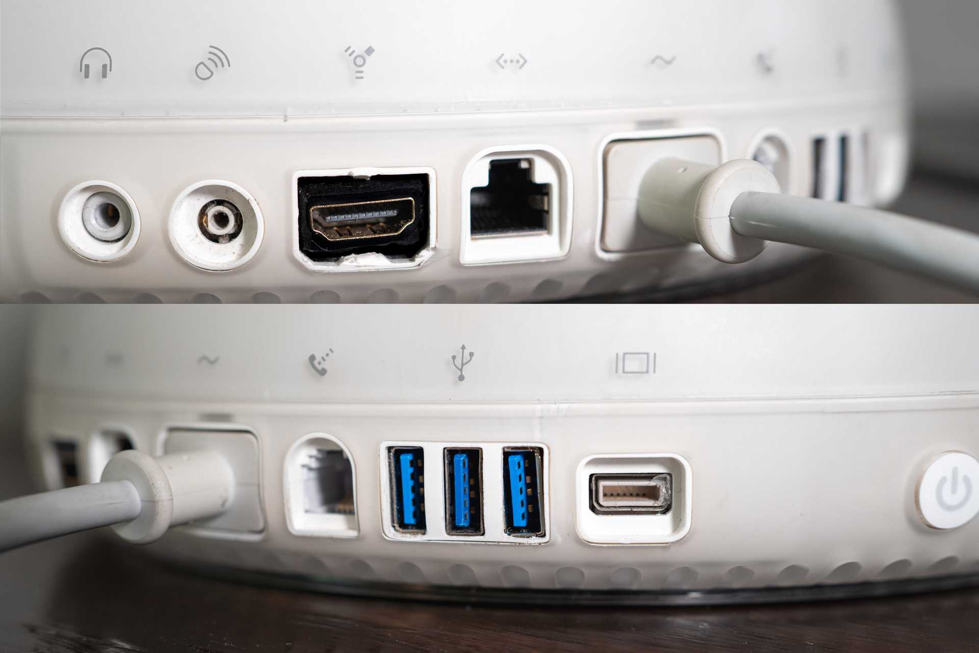
The port array on the back seems reasonably comprehensive at the time — other than the display interface. It's got 3 USB 1.1 ports (2.0 had just come out and wasn't adopted to the iMac until 2003), 2 Firewire 400 ports, an Apple Pro Speakers mini-jack, a phone jack for the 56k modem, a 100Mbps ethernet port, and a headphone jack. Experts speculate that the headphone jack was included simply so that when the 2003 model with optional bluetooth was released AirPod users would want to upgrade. However, there appears to have been a lack of communication between development teams since that module used Bluetooth 1.1 and the AirPods require at least 4.0. Crazy.
The teardown
This is just an overview of the process; if you're trying to recreate the mod, I highly recommend Dremel Junkie's website above.
I started by taking off the front of the display assembly, which houses the LCD panel and the backlight inverter, just to see what I was working with. Immediate disappointment. Not only was I getting no readout from the inverter on my multimeter, but I also found that the LCD was using a TDMS connection. This is a standard that powers both DVI and HDMI but is pretty uncommon as an internal display driver compared to LVDS.
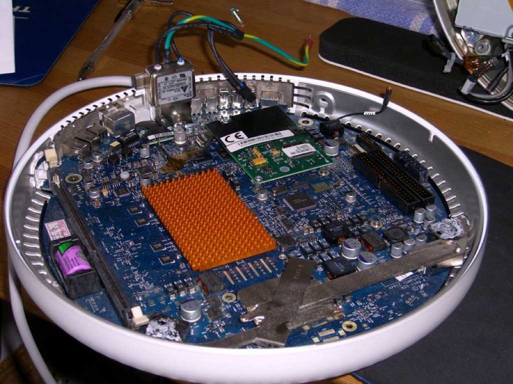
On to the dome. Under the access plate (which incidentally is the only spot not using torx screws), we find the user-upgradeable RAM and airport card. I find it interesting that the internal RAM slot is a full length 135mm DIMM slot, but the one accessible by the user is a ~70mm SODIMM slot. I'm not sure that I've encountered mixed RAM form factors before, though I would imagine that giving the user access to only one slot for expansion was intended to 'simplify' the upgrade path.
Image courtesy Dremel Junkie
The bulk of the space in the dome itself is taken up by the storage block, which is an aluminum cage with a disk drive mounted to one side and the 3.5" HDD mounted to the other. Though the tongue-out CD drive is cute, I would need to replace it since the original has an IDE interface, plus it takes up a ton of space, so I opted to scrap my dreams of circular storage mediums. I saved the hinging mechanism for the drive door in case I change my mind some day and want to rebuild it, but it's entirely aesthetics since I usually don't have much use for a disk drive.
Also contained in the dome is the power supply mounted on the side, an 80mm case fan, the Apple chime speaker, and a bunch of wires coming from the goose neck.
At this point I realized how much space I actually had to work with, and that just sticking in a Pi and display controller might be underkill.
Introducing the Intel NUC!
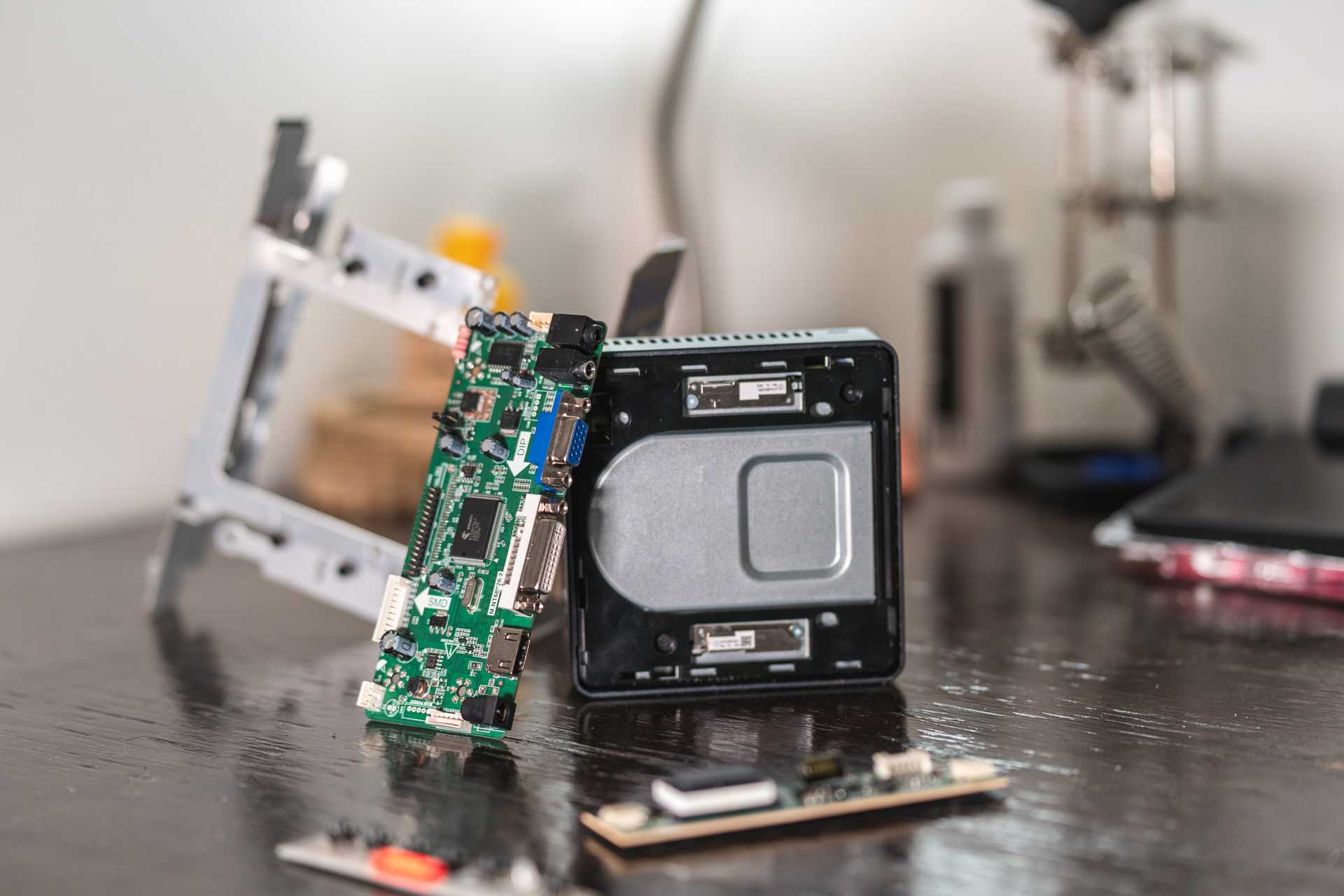
This little guy packs a punch at 115x111x36mm in its enclosure. It's basically laptop brains in a box with many features typically only available on desktop boards like extra USB/panel headers, serial headers, and no touchpad.
NUC with display control board and cage
The idea for using a NUC came from this Quinn Nelson video, and the majority of the hackintosh process for them is documented on TonyMac x86 (though I still had to do a lot of troubleshooting to get it to actually work).
The build
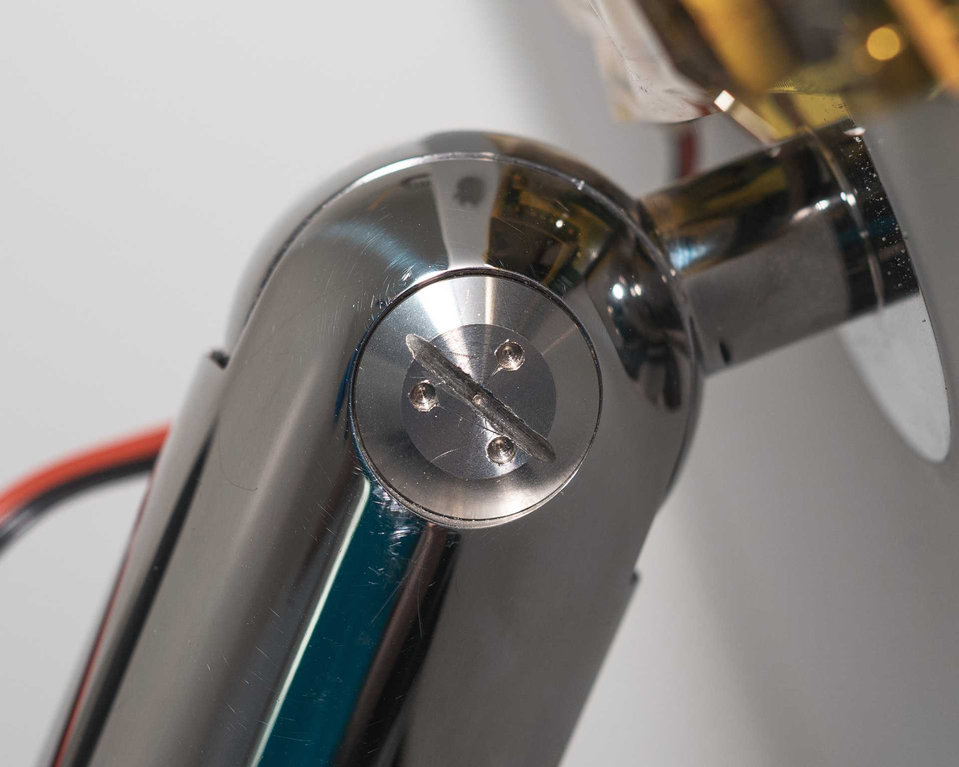
'tis but a scratch
Image courtesy Dremel Junkie
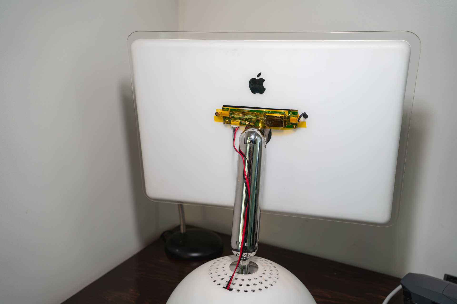
At least you can't see it from the front
Perhaps overkill but it works
HDMI port might still need some work
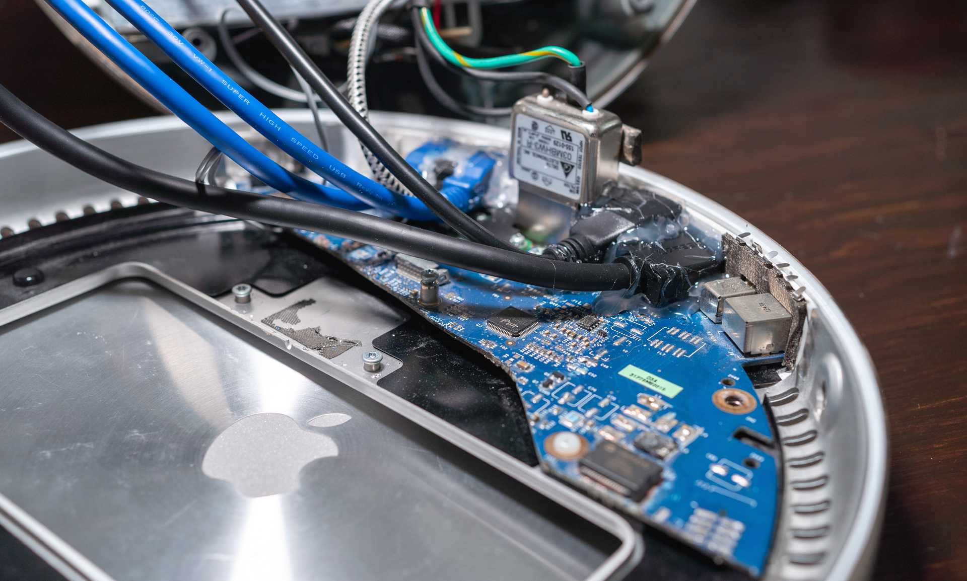
I wasn't using anything on the original motherboard besides the rear I/O, and I hadn't used the Dremel in several minutes, so I got it back out and cut the whole thing in half.
It took a whole team to make it round, but 5 minutes with a Dremel to undo it
The ethernet port got a similar treatment to USB. I fitted a cat-6 RJ45 extender that ran to the 1Gbps port on the NUC. The last main port I cared about was HDMI. The extender end wouldn't fit where the mini-VGA port was, but after cutting out the plastic column between the dual Firewire ports it fit there just fine. My last alteration was adding some wires to the momentary switch behind the original power button so that it could still be used. For now I left the mini-VGA, DSL, Pro Speaker, and headphone jacks alone since I didn't have anything better to put there. I'd like to use the original headphone jack, but at the moment my macOS install isn't working with HDMI audio output, so I'm going to try to fix the software before I do the hardware. I do have audio through this USB audio adapter, so if all else fails I might just put that inside and wire it to the built-in headphone jack.
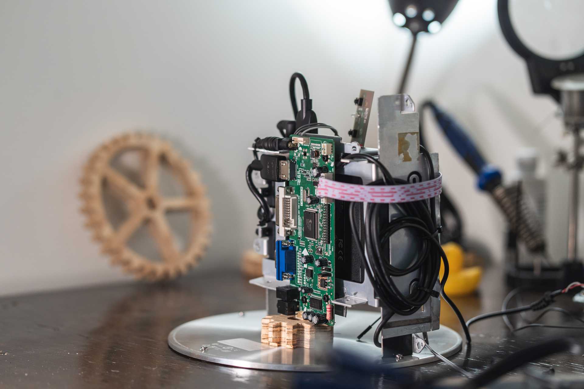
The "Guts": Display board, power supplies, and NUC mounted to the cage
The final touch before shoving everything in was to add a monitor power button and light to the front. Since at the moment I'm not using the disk drive door, I sealed it to the surrounding plastic, added an indicator LED behind it to glow through, and cut a small hole for a tact switch. These got wired to the display control board. I thought about doing this for all of the OSD buttons that the control board exposes, but I don't see myself messing with the OSD controls enough to justify further ruining the clean finish on the front.
Time to put it all together. The original power button got wired to the fan header before I closed up the NUC, so I left some slack on it so that I could still work on the two halves separately while putting in the main block. I left a lot less slack on the LVDS wires coming from the goose neck so that there wouldn't be anything to get caught in the fan, so I plugged those in as I was lowering the block into the dome. After that, I just needed to plug in all of my port extenders, wire the two power supplies into the original AC plug, and cable manage enough to safely close the bottom.
Software
This was my first venture into Hackintoshes, but between the TonyMac guide linked above and others (including this good one from Hackintosher) I was able to get it up and running in a couple of hours with most things working. For simplicity's sake I got most of the kinks worked out before actually sticking the NUC into the dome.
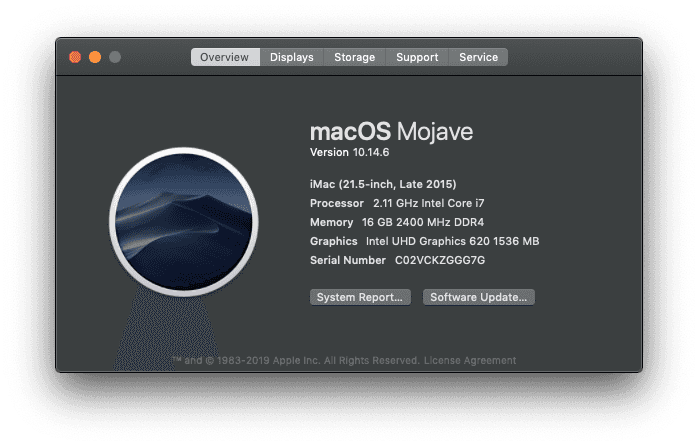
Version info; the G4 is running the latest version of Mojave
- USB Audio
- USB/HDMI ports
- Ethernet
- WiFi
- Sleep and Wake
- App Store, iMessage
Not Working:
- HDMI Audio
- Bluetooth (no bluetooth adapter)
- DSL 56k modem
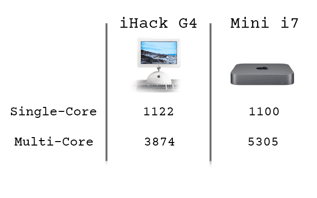
I don't want to talk a lot about the benchmarks, because this is first and foremost a project about giving new life to a beautiful old machine.
She does hold her own though.
I compared it to a late-2018 Mac Mini with an i7-8700B that was benchmarked on Geekbench. It's worth noting that the Mac Mini compared only has 8GB of ram, but it also has a 6-core desktop i7, so that heavily influences the multi-core score.
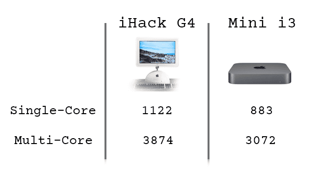
Perhaps a more fair comparison is against the i3 Mac Mini, which retails for $799, only a few hundred dollars more than this build. It has a 4-core desktop i3 and 8GB of ram.
Would I be willing to pay an extra $200 for something less powerful that doesn't look as cool? No.
If you've done/want to do a project like this or if you have any questions or comments, please reach out!

